Title here
Summary here
This page is still work in progress. Improve the site by filing a pull request on GitHub. Switzerland and US purchase links are listed below; please add other international links via a PR.
This page lists hardware for two common setups:
Minimal setup (required): Enough to run OpenCCA on an RK3588 ROCK 5B
Box with Flashserver (optional): A small lab setup that supports remote UART access, automated flashing, and power cycling.
To get started with OpenCCA, you need the parts below.
| Product | Link | US Link | Comment |
|---|---|---|---|
| Radxa ROCK 5B (RK3588) | AliExpress | Amazon | Recommended: 16 GB RAM |
| eMMC (16 GB+) Radxa eMMC | AliExpress | Amazon | The microSD slot is multiplexed with SWD, so eMMC is recommended. See: Info on SD card |
| Power supply Anker Nano II 65W | Amazon (DE) | Amazon | Not every USB-C power supply works reliably. See: Radxa power supply discussion |
| USB to TTL adapter (3.3 V) | AliExpress | Amazon | A CH340G (3.3 V) (Baudrate 1.5 Mbps) See: Connect to UART |
| USB-C cable | generic | Amazon | Cable for power to RK3588 |
Once you purchased the parts, build and flash the firmware
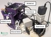
For automated power cycling and flashing, we built a small box setup.
You find a docker container with all scripts for the management node in opencca-flash.
| Product | Link | US Link | Comment |
|---|---|---|---|
| Raspberry Pi 5 | Digitec (CH) | Amazon | We recommend model 5. Install Raspberry Pi OS. |
| Raspberry Pi Power Supply (27 W) | Digitec (CH) | Amazon | |
| MicroSD card (for Raspberry Pi) | Digitec (CH) | Amazon | Storage for the Raspberry Pi. |
| Ethernet switch | Digitec (CH) | Amazon | Optional |
| 2 short patch cables | Digitec (CH) | Amazon | Connect Pi + ROCK 5B to the switch. |
| 1 longer patch cable | Digitec (CH) | Amazon | Uplink to your network. |
| USB-C -> USB-A adapter | AliExpress | Amazon | Connect USB-C dock to Pi USB-A port |
Connect the USB-C dock to the Raspberry Pi. Connect the RK3588 to the dock as a peripheral. Finally, power the dock through its USB-C PD port with an external power supply.
| Product | Link | US Link | Comment |
|---|---|---|---|
| Anker PowerExpand 6-in-1 USB-C | Amazon (DE) | Amazon | The ROCK 5B multiplexes power + data on one USB-C port. A dock helps you power the board and flash firmware without cable juggling. See: Radxa power supply discussion |
| USB-C cable | generic | Amazon | Cable for power to RK3588 |
In our setup, the Raspberry Pi can still back-power the RK3588 over USB. That means toggling the smart plug alone may not fully reset the board as the the RK3588 can stay partially powered via the USB hub.
To get a true hard reset, we do
With both power sources removed, the RK3588 performs a reliable hard reset.
| Product | Link | US Link | Comment |
|---|---|---|---|
| Smart plug | Athom (EU) | Amazon | Remote power cycling for reflashing. Any smartplug will work that exposes HTTP API. We used Tasmota Firmware. |
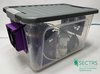
Optional enclosure parts to house the setup, including a power strip and fans.
| Product | Link | US Link | Comment |
|---|---|---|---|
| Power strip | Digitec (CH) | Amazon | |
| Plastic box | Digitec (CH) | Walmart/Target | Optional enclosure. 37.5 x 25 x 23 cm, 15 l or larger. |
| Step-up converter (optional) | AliExpress | - | Optional, e.g. for quieter fan control. |
| 12 V or 5 V fan (optional) | generic | generic | Optional cooling. |
| Glue, tape, wood or cardboard and rubber bands | generic | generic | For assembly, see pictures |
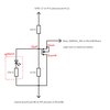
The MOSFET circuit is not strictly necessary. You can flash the firmware manually by pressing the physical button on the SoC. However, if you plan to do this thousands of times (like we did during the initial bring up), it may be worth automating this. We soldered a simple circuit to the board to bypass the physical button, using a MOSFET as a programmable switch controlled via a Raspberry Pi GPIO pin.
Wiring (example GPIO17):
| Product | Link | US Purchase Link | Comment |
|---|---|---|---|
| Circuit board | AliExpress | Amazon | For a Maskrom automation circuit. |
| Soldering Toolkit | - | Amazon | Recommended for assembly. |
| MOSFET IRLZ44N | AliExpress | Amazon | |
| 10kΩ resistor + 220Ω resistor | - | Amazon | |
| Cables | AliExpress | Amazon | Breadboard jumpers. |
| LED | - | Amazon | Optional status indicator. |
You find instructions on how to obtain and print the 3D models in the opencca-box repository.